
Tutorial – communication with RS232
How to control the electronic v2 board from the serial port RS232
Communication protocol : RS232.
Communication speed : 9600 bauds
Configuration : 8 bits, no parity, 1 stop bit
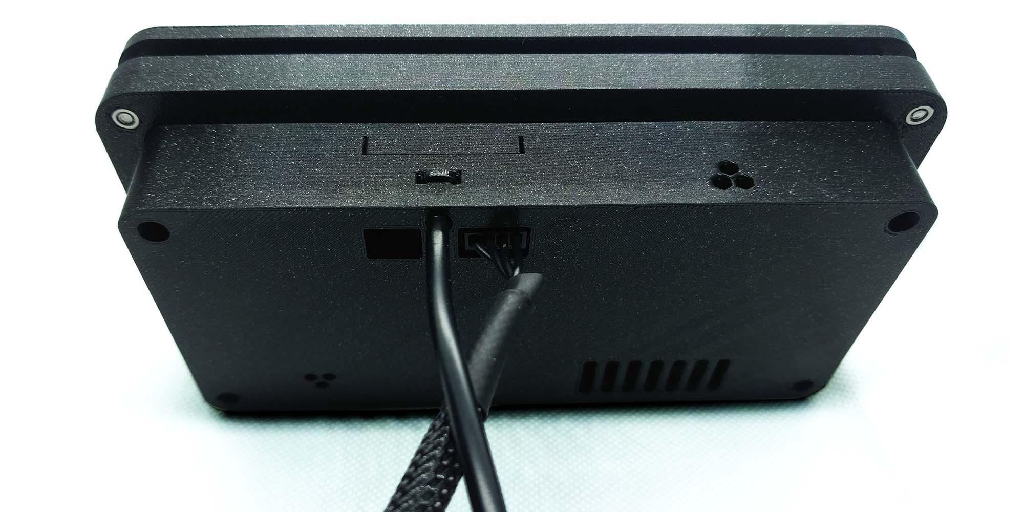

Description of pins on the board Alveo3D V2 :
View from the backside of the board.
GND_v2 : common mass.
Rx_v2 : Rx v2 board,
Data reception :
The voltage signal must not exceed 5VDC.
Tx_v2 : Tx v2 board,
Data transfer :
The v2 Tx output is compatible with Raspberry Pi Rx entry,
The voltage signal output is 3.3VDC.
1. Connect board v2 to Raspberry
The 4 pins connector on the black cable must link the v1 board from the filtering case to the electronic board v2.
The RS232 connection from the board v2 is direct,
we are suggesting two methods to set the communication between the board v2 and the Raspberry.

First method : GPIO
This way will use the Raspberry Pi GPIO port :
NOTICE : In the current Raspberry design, it is not possible to use the UART and the Bluetooth at the same time.
It is necessary to disable the Bluetooth. If you need Bluetooth we advise you to use the second method.
Wiring :
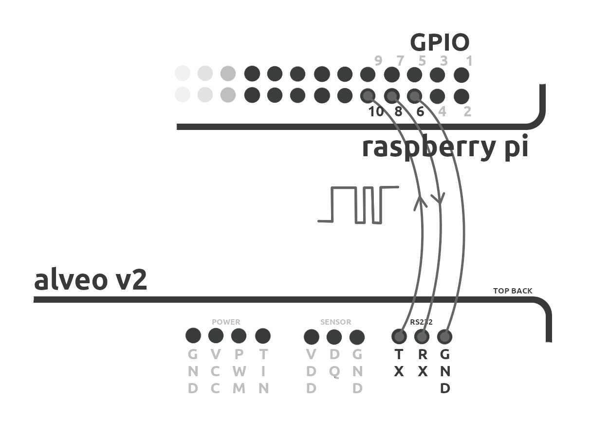
ALVEO V2 RPI
TX_v2—————————— RX
RX_v2—————————— TX
GND_v2————————— GND
Connect with a simple wire :
Pin TX_v2 to RX RPI : pin #10 (GPIO15).
Pin RX_v2 to TX RPI : pin #8 (GPIO14).
Pin GND_v2 ( ground ) on one of the available grounds RPI GPIO port :
RPI2 : pin #06, #09, #14, #20 or #25.
RPI3 : pins RPI2 + pin#30, #34 or #39.
Second method : converter RS232/USB
This method will be based on a converter RS232/USB (USB to UART bridge) (follow the industry-standard FTDI TTL cable interface).
It can be connected to a USB port on Rpi or on a PC.
Available on Amazon, eBay, RS-components….
Example: UM232R, LC234X…
Wiring :
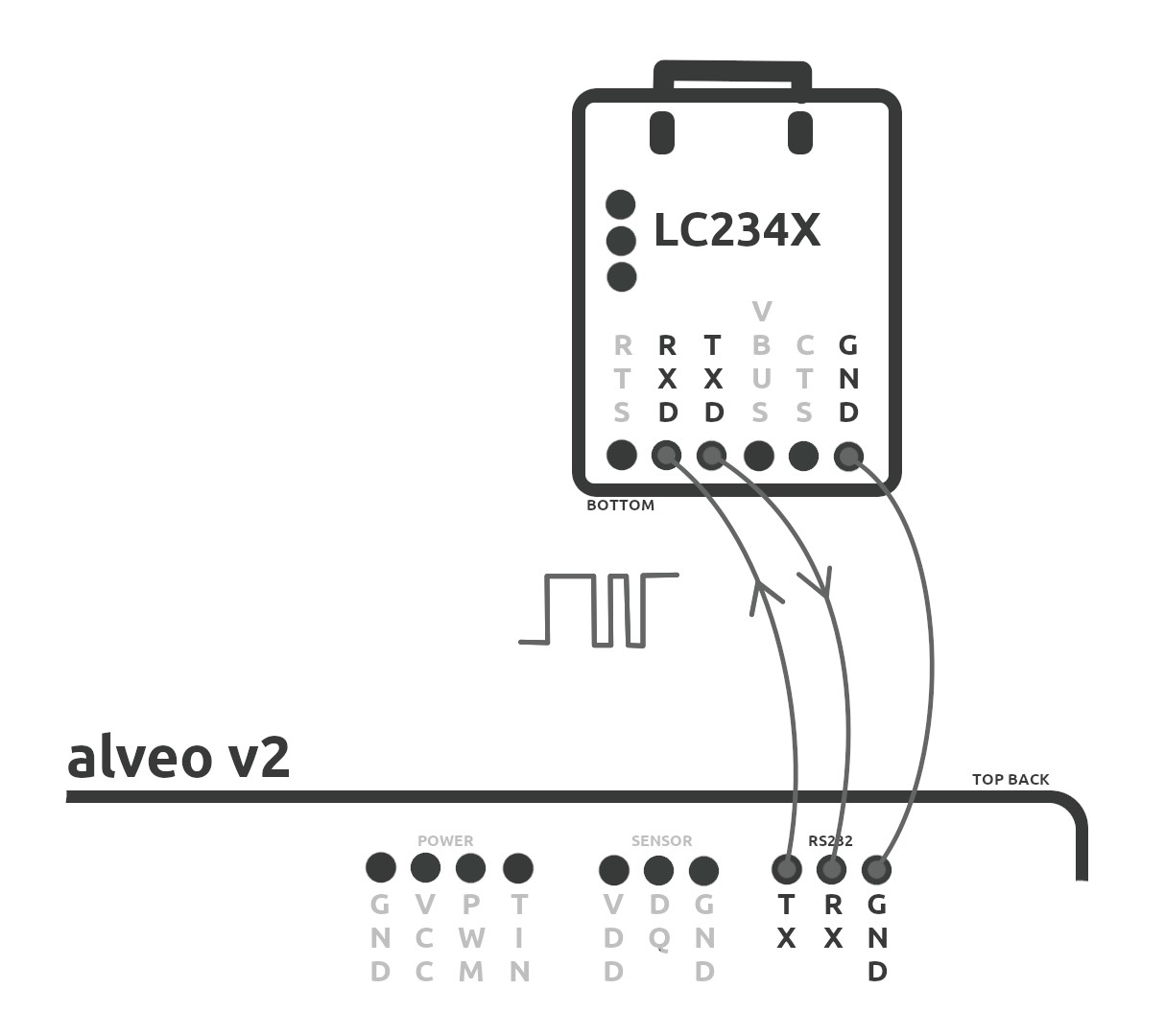
WIRING EXAMPLE WITH A LC234X
ALVEO V2 LC234X
TX_v2——————————– RX
RX_v2——————————– TX
GND_v2—————————– GND
Connect with a simple wire :
Pin TX_v2 to RXD on LC234X
Pin RX_v2 to TXD on LC234X
Pin GND_v2 (ground) to pin GND on LC234X.
For this tutorial, we will use this method with the
Converter LC234X :


2. Configure the electronic board v2 :
To enable the serial link between the Raspberry and the electronic board v2 you must enable the option Rs232 in the menu Options v2.
In the main menu go to “Settings”.

In the menu “Settings” go to “Options v2”.

In the “Options v2” scroll down to “Rs 232”.

Enable the serial link “Rs 232” by clicking “OK” to turn “Rs 232” to “On”.

All commands from the Rs232 can be sent while you are navigating in the v2 menu but the information feedback in the screen console ‘step 3.4) can only be done when the v2 interface is set on the main screen.
Now your v2 is ready you can turn on your Raspberry Pi, when you are the desktop proceed the following steps :
3.1 – Launch a terminal on the raspberry :

3.2 – Update the repositories :
pi@raspberry:-$ sudo apt-get update
update the packages :
pi@raspberry:-$ sudo apt-get upgrade
Install screen in a terminal :
pi@raspberry:-$ sudo apt-get install screen
3.3 – Find the connection port needed (ttyUSB0 mostly)
in the folder /dev/
pi@raspberry:-$ cd /dev && ls -lh

3.4 – Start screen in a terminal indicating port and port speed
pi@raspberry:-$ screen /dev/name_of_your_port 9600

Screen console will show up :

You should receive feedback from the v2( values just for example ) :
>>> #command:value# 0.50% 3h 3000rpm 50.0% 15min 29°C
Last command | filter saturation in % | filter saturation in hours | fan speed | PWM | Timer | Temperature
if nothing is displayed on the console that means you are not on the main screen in the v2 board. You can also check if the communication with the v2 is working by pressing semicolon “;” it should return a response in the screen console.
It is important to close screen console properly : you should press ctrl+a then \ then validate with y (it is important to free the USB port ttyUSB0)
4. Commands list :
All commands must be approved by a “;” (not enter key)
pour all commands with an attached value, they must be separated by a “:”
4.1 – To send a command in screen, you just need to write “command_name;” :

In a screen console, you will not see what you are typing but for each command, you will get a response in the console :

It is important to close screen console properly : you should press ctrl+a then \ then validate with y
Fin the commands list below:
COMMANDS :
m3
m3
timer
start
stop
pwm
pwm
runt
temp
fast
buzzer
backlight
rpm
settings
lang
opt1
opt2
VALUES min-max :
–
–
0.0, ~
0.0, ~
–
–
0.0%, 100%
0, 1023
–
–
–
0/1
0/1
0/1
–
fr/en
0/1
0/1
Display the commands list
Show dimensions in dm3 with the minimum filtering time
Update the value in dm3 (see Ex.1)
Set the timer in minutes our hours (see Ex.2)
Start the fan
Stop the fan
Change the power in % (see Ex.3)
Change the power in decimal from 0 to 1023 (see Ex.3)
Show the running time
Show the temperature in °C
Launch the fast clean mode
Dis/enable buzzer option
Dis/enable backlight option
Change algorithm to calculate RPM 0 = axial / 1 = blower (3000 rpm)
Show full settings list
Change language
Dis/enable option 1 (check manual v2)
Dis/enable option 2 (check manual v2
Example of commands :
For the timer commands you can write timer:xxH; or timer:xxh, “h” in capital or lower-case.
timer:2H;
timer:1h30;
timer:2H30;
timer:10m
timer:20M;
start;
pwm:512;
pwm:10%;
stop;
fast;
m3:216;
Configure the timer for 01H00
Configure the timer for 02H00
Configure the timer for 01H30
Configure the timer for 02H30
Configure the timer for 00H10
Configure the timer for 0H20
Start fan with the defined power
update the PWM value, here 512 = 50% (1024 = 100%)
update the PWM value, here 10%
Stop fan
Start FAST mode, the time will be adjusted automatically
Change and save the new enclosure dimension in dm3
Feel free to share your ideas and your comments to improve our solutions
Talk to us on the online chat or by sending us an email.

KNOW-HOW
Made in France from Alps

European countries
Shipped from France

CONTACT
+33 616 806 403 [email protected]